- 您现在的位置:买卖IC网 > Sheet目录323 > DV164101 (Microchip Technology)KIT DEV PICKIT1 FLASH 8/14PIN
PICkit ? 1 Flash Starter Kit User’s Guide
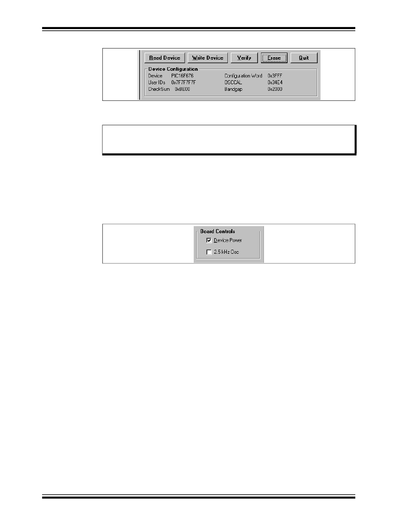
FIGURE 2-12:
DEVICE CONFIGURATION
For more information on the OSCCAL and bandgap calibration, see the device data
sheets located on the CDROM or the Microchip web site (www.microchip.com).
Note:
2.2.10
The “Regenerated OSCCAL” and “Set Bandgap Calibration Value”
functions are only available on the PIC12F629/675 and PIC16F630/676
devices.
2.5 kHz OSC
The 2.5 kHz OSC is a square wave signal that, when selected, is input to pin 3 of the
evaluation socket. See the schematic Figure A-1 in Appendix A.
DS40051D-page 12
FIGURE 2-13:
BOARD CONTROLS
? 2004 Microchip Technology Inc.
发布紧急采购,3分钟左右您将得到回复。
相关PDF资料
DV164120
KIT STARTER PICKIT 2
DV164121
KIT PICKIT 2 DEBUG EXPRESS
DV164122
ANALYZER SRL PICKIT W/DEMO BOARD
DV164131
KIT STARTER PICKIT 3
DV164132
KIT EVAL F1 FOR PIC12F1/PIC16F1
DV243003
KIT STARTER FOR SRL MEM PRODUCTS
DVA1001
ADAPTER FOR PIC16F716 18DIP
DVA1004
DEVICE ADAPTER 8/14/20DIP
相关代理商/技术参数
DV164101
制造商:Microchip Technology Inc 功能描述:TOOLS: FLASH MICROCONTROLLER (
DV164102
功能描述:开发板和工具包 - 无线 rfPICkit RoHS:否 制造商:Arduino 产品:Evaluation Boards 工具用于评估:AT32UC3L 核心:AVR32 频率: 接口类型:USB 工作电源电压:5 V
DV164120
功能描述:电路内置调试器 PICkit 2 8/14/20P Flash RoHS:否 制造商:Microchip Technology 产品:In-Circuit Debugger Kits 工具用于评估:PIC MCUs, dsPIC DSCs 用于:07-00024, AC164113 核心:dsPIC, PIC 接口类型:USB 工作电源电压:3 V to 5 V
DV164121
功能描述:电路内置调试器 PICkit 2 Debug Express RoHS:否 制造商:Microchip Technology 产品:In-Circuit Debugger Kits 工具用于评估:PIC MCUs, dsPIC DSCs 用于:07-00024, AC164113 核心:dsPIC, PIC 接口类型:USB 工作电源电压:3 V to 5 V
DV164121
制造商:Microchip Technology Inc 功能描述:ICPICKIT2 PROGRAMMER/DEBUGGER ((NW))
DV164121+TEFLCST3
制造商:Microchip Technology Inc 功能描述:KIT PICKIT2+FLOWCODE-HOME BUNDLE 制造商:Microchip Technology Inc 功能描述:ICD, PICKIT 2, FLOW CODE, PIC, DSPIC 制造商:Microchip Technology Inc 功能描述:ICD, PICKIT 2, DEBUG EXP, FLOW CODE, PIC, DSPIC; Silicon Family Name:PIC12F6xx, PIC16F5xx; Core Architecture:PIC; Core Sub-Architecture:PIC12, PIC18, PIC24; IC Product Type:Debugger / Programmer; Series:PICkit 2 ;RoHS Compliant: Yes
DV164122
功能描述:界面开发工具 PICkit Ser Analyzer RoHS:否 制造商:Bourns 产品:Evaluation Boards 类型:RS-485 工具用于评估:ADM3485E 接口类型:RS-485 工作电源电压:3.3 V
DV164126
功能描述:开发板和工具包 - PIC / DSPIC USB Kit w/ PICkit LowPinCount RoHS:否 制造商:Microchip Technology 产品:Starter Kits 工具用于评估:chipKIT 核心:Uno32 接口类型: 工作电源电压:
